The pulse width modulation motor control printed circuit board allows a finer degree of control over the EMF magnitudes driving a standard coil wrapped, brushed DC motor, in comparison to the alternative method of potential division and graduation.
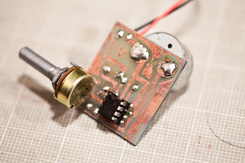
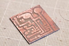
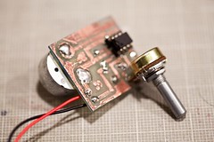
In essence, the precipitation of copper within an aqueous copper chloride solution, removes unmasked areas of the copper clad fibre-glass substrate (masked using a Xylene based indelible solution), revealing tracks with negligible resistance to which two 100 nf polyester caps are affixed with flux core solder along with a potentiometer, which acts as the circuit input. But the heart of the circuit resides within the dual in-line IC package, where we find the ubiquitous 555 timer, configured to oscillate in an astable manner using the aforementioned components. The oscillations allow for a modulation of the DC duty cycle supplied by the circuit, which in turn allows a fine degree of control over the cyclical movement exhibited by the motor.
OR
This thing's made of stuff from the Internet all stuck together onto a piece of plastic and it turns the motor on and off really quickly. If you change how often you turn the motor on and off, you can make the motor go faster or slower.
No comments:
Post a Comment